How to Solve the Electricity Review Maze with Accurate Solutions
Focus on understanding the core principles behind each electrical problem before attempting to solve it. Analyze the circuit layout carefully and identify the key components involved. Knowing the role of each part, such as resistors, capacitors, and conductors, will help in making informed decisions.
Work through the challenges step by step, instead of jumping to conclusions. Begin by isolating simple connections and gradually build upon your understanding of the more complex parts. This approach will lead to clearer insights and reduce the chances of errors.
Double-check your work by retracing the path of electrical flow in the puzzle. Ensure that each connection is logically placed, and verify that the sequence of electrical components makes sense. Mistakes in sequencing or missed connections are common, so being methodical can help avoid them.
Use common sense and deductive reasoning to eliminate incorrect pathways. If a solution seems illogical or leads to an incorrect result, reconsider your approach. Simplifying the problem can often reveal the correct path more quickly.
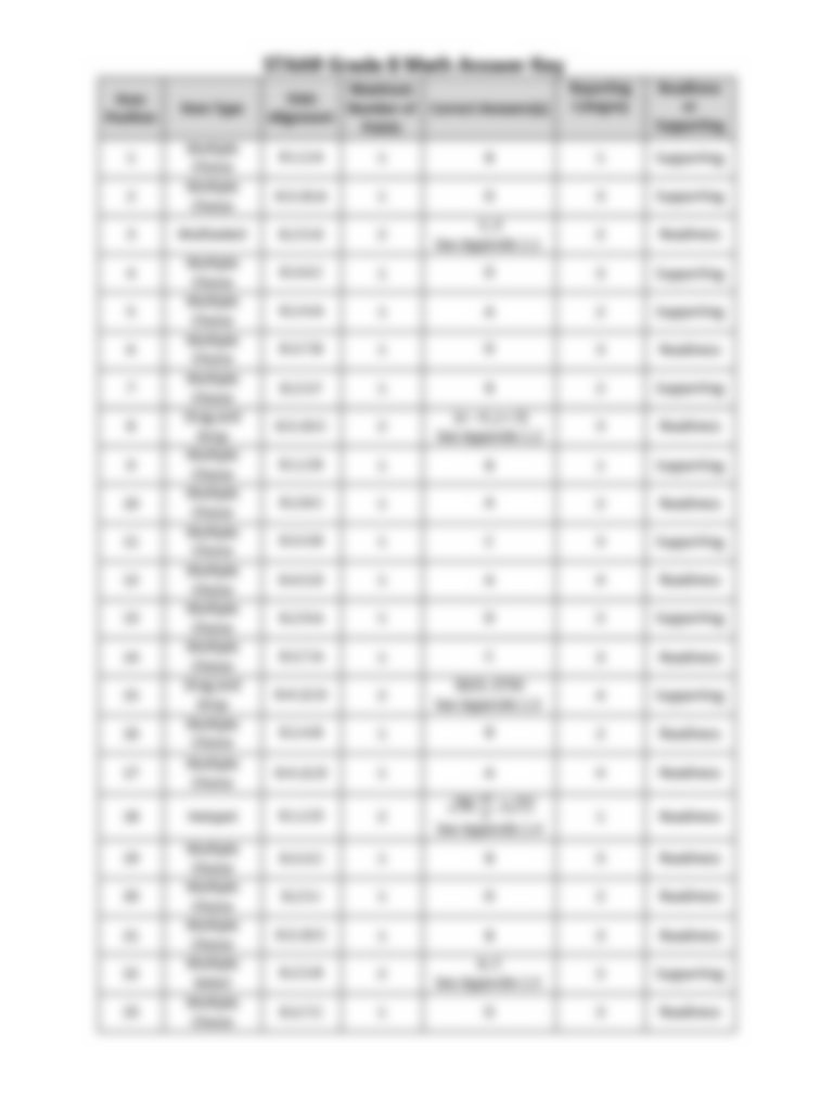
Electricity Review Maze Answer Key
Focus on identifying the circuit components in the puzzle, such as resistors, capacitors, and switches. Understanding the behavior of each part is critical for determining the correct flow.
Follow the path of current flow step by step. Begin by tracing the initial connection, then proceed through each element logically, ensuring that every transition aligns with the principles of electrical circuits.
Double-check the connections. Often, the correct path is blocked by an overlooked switch or misplaced wire. Take the time to verify every element and ensure that the connections between components are correctly made.
Use trial and error strategically. If an attempted path doesn’t work, backtrack to the last known correct decision point and try an alternative. This iterative approach helps in narrowing down the options.
Understanding the Basic Principles of Electrical Circuits
Current flows through conductors like wires in a complete circuit. This flow is driven by a voltage source, such as a battery or power supply. The voltage creates an electrical pressure that pushes the current through the circuit.
Resistors limit the flow of current. Their purpose is to control the amount of current passing through a specific part of the circuit. The resistance depends on the material, length, and thickness of the resistor.
Series and parallel configurations determine how components are arranged in the circuit. In a series circuit, components are connected one after the other, so current must pass through each component. In a parallel circuit, components are connected across common points, allowing multiple paths for the current to flow.
Ohm’s Law governs the relationship between voltage, current, and resistance. It is expressed as V = I × R, where V is voltage, I is current, and R is resistance. This law helps to calculate and understand the behavior of circuits.
Power is consumed in the circuit based on the amount of current flowing and the voltage applied. Power is calculated using the formula P = V × I, where P represents power, V is voltage, and I is current.
Step-by-Step Guide to Solving Electrical Puzzle Challenges
Step 1: Begin by identifying all the components in the puzzle. Look for symbols like wires, switches, and power sources. Recognizing the components is the first step to understanding how they interact within the puzzle.
Step 2: Analyze the layout. Follow the path of connections to see how each component is linked. This will help you visualize the flow of current and how to complete the circuit.
Step 3: Check for open connections or shorts. Make sure all paths are correctly connected and there are no gaps where the current can’t flow. A broken or open connection may prevent the circuit from functioning properly.
Step 4: Understand how the components affect each other. For example, resistors limit the current flow, while batteries provide the necessary voltage. Determine how these components will influence the behavior of the entire system.
Step 5: Apply simple formulas. Use basic principles to calculate unknown values like voltage, current, or resistance, if applicable. This can help clarify the relationships between components and ensure you’re on the right track.
Step 6: Consider alternative solutions. If the puzzle isn’t progressing as expected, explore different configurations or component placements. Sometimes, changing the arrangement can lead to a valid solution.
Step 7: Review your solution. Check all connections and calculations to ensure everything is correct. Small mistakes, like incorrect connections or miscalculations, can prevent the puzzle from being solved.
Common Mistakes to Avoid in Circuit Challenges
1. Incorrect Component Orientation: Ensure that all components like resistors, capacitors, and diodes are correctly oriented. Misplaced components can lead to incorrect functionality and invalidate your solution.
2. Overlooking Current Direction: Double-check the direction of current flow, especially in components like diodes or transistors. Reversing the direction can lead to malfunctioning circuits.
3. Skipping Connections: Verify that all necessary connections between components are made. Missing a single link in the circuit can prevent the system from working as expected and affect your ability to solve the puzzle.
4. Misunderstanding Component Ratings: Ensure that each component’s voltage and current ratings match the requirements of the puzzle. Incorrect ratings can cause components to fail or operate inefficiently.
5. Failing to Account for Parallel and Series Configurations: Understand the difference between parallel and series circuits. Mistaking one for the other can drastically change the behavior of the system and make it impossible to reach the correct solution.
6. Ignoring Power Sources: Confirm that the power sources are correctly placed and are providing the right amount of power. Incorrect power supply can disrupt the circuit’s performance or lead to errors.
7. Overcomplicating the Solution: Keep the design simple. Often, the simplest circuit configuration will achieve the desired outcome more efficiently than complex setups.
8. Not Double-Checking for Short Circuits: Always check for potential short circuits, especially when dealing with power sources. A short circuit can render the entire system inoperable and prevent solving the task.
How to Identify Key Electrical Components in the Challenge
1. Identifying Resistors: Resistors can be recognized by their rectangular shape with color bands. These components limit the flow of current in the circuit and are often used to adjust voltage levels or protect other components.
2. Recognizing Capacitors: Capacitors are typically cylindrical or rectangular components with two leads. They store electrical charge and are used to smooth voltage fluctuations or to filter signals in the circuit.
3. Spotting Diodes: Diodes have a distinctive shape, often with a line marking one end, and allow current to flow in only one direction. They are used to control the direction of current flow and prevent damage from reverse voltage.
4. Understanding Transistors: Transistors are small, usually square or rectangular, components with three leads. They function as switches or amplifiers and can control current flow between different parts of the circuit.
5. Recognizing Inductors: Inductors appear as coils of wire and store energy in the form of a magnetic field. They are often used to filter or store electrical energy in circuits involving alternating current.
6. Identifying Switches: Switches can be simple mechanical devices or digital components that control the flow of electricity. Look for devices that open or close the path for current based on user input or automated logic.
7. Locating Ground Connections: The ground in a circuit is typically indicated by a symbol resembling an inverted triangle with a line beneath it. It is a reference point for the circuit’s voltage and helps in stabilizing the system.
8. Recognizing Power Sources: Power sources such as batteries or power supplies are often labeled with their voltage and current ratings. They are the starting point of current flow in the circuit.
Tips for Navigating Complex Wiring Problems
1. Start with a Clear Plan: Before attempting to solve any wiring problem, take the time to sketch out the layout. This will give you a visual guide of how everything is connected, making it easier to identify potential issues.
2. Test Components Independently: Use a multimeter to test individual components like resistors, capacitors, or switches. This will help you confirm whether the problem lies in a specific component, allowing for a more focused troubleshooting approach.
3. Avoid Overloading Circuits: Overloaded circuits are common in complex setups. Always check the power rating and ensure you’re not exceeding the capacity of any components. This step can prevent short circuits or blown fuses.
4. Check for Loose Connections: Loose or improper connections are one of the most common causes of electrical failures. Tighten any loose wires and ensure that each connection is secure and well-insulated.
5. Inspect Grounding and Short Circuits: Improper grounding or short circuits can lead to dangerous situations. Make sure all components are grounded correctly and that there are no exposed wires causing a short circuit.
6. Work in Segments: Break down the wiring system into manageable sections. Test each section individually to isolate the faulty area more easily. This systematic approach can speed up the process and reduce the risk of overlooking key problems.
7. Use Correct Tools: Ensure you’re using the appropriate tools for cutting, stripping, and connecting wires. Using the wrong tool can damage the components or create unsafe connections.
8. Consult Reliable Resources: If you’re unsure, refer to trusted websites like Electronics Tutorials for more information and detailed guides on troubleshooting complex circuits.
| Tip | Why It Helps |
|---|---|
| Start with a Clear Plan | Provides a visual guide to help understand the circuit layout and identify issues. |
| Test Components Independently | Helps isolate problems by confirming the functionality of individual parts. |
| Avoid Overloading Circuits | Prevents overheating or damage caused by exceeding the power rating. |
| Check for Loose Connections | Prevents power loss or malfunction caused by insecure or exposed connections. |
| Inspect Grounding and Short Circuits | Protects against electrical hazards and potential damage. |
| Work in Segments | Allows for quicker isolation of the problem by focusing on smaller sections. |